
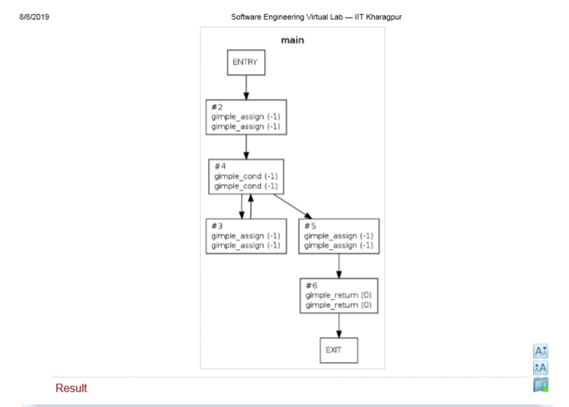
A control flow graph (CFG) is a directed graph where the nodes represent different instructions of a program,
and the edges define the sequence of execution of such instructions.
A program, however, doesn’t always consist of only sequential statements. There could be branching and
looping involved in it as well. Figure 1 shows how a CFG would look like if there are sequential, selection and
iteration kind of statements in order.
A Control Flow Graph (CFG) is the graphical representation of control flow or computation during the execution of programs or applications. Control flow graphs are mostly used in static analysis as well as compiler applications, as they can accurately represent the flow inside of a program unit. The control flow graph was originally developed by Frances E. Allen.
Characteristics of Control Flow Graph:
- Control flow graph is process oriented.
- Control flow graph shows all the paths that can be traversed during a program execution.
- Control flow graph is a directed graph.
- Edges in CFG portray control flow paths and the nodes in CFG portray basic blocks
output- https://drive.google.com/open?id=1P3IzI1bVh5XvmNxfCMjXvVh_wQphliCS
https://drive.google.com/open?id=1Caygmh3fxjN8o05mNVULvu1WuooAL-OU
Computing Cyclomatic Complexity
Let G be a a given CFG. Let E denote the number of edges, and N denote the number of nodes. Let V(G) denote the
Cyclomatic complexity for the CFG. V(G) can be obtained
V(G) = E – N + 2
